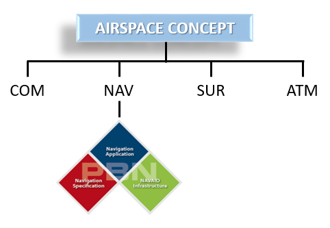
The PBN concept is made up of three components which together with Communication, Surveillance and ATM systems and procedures enable the Airspace Concept. The three PBN components are:
The Navigation Application - which is enabled by:
- The Navigation Infrastructure
- The Navigation Specification
The Navigation Application refers to routes and instrument flight procedures (IFPs) which have navigation performance requirements determined by the needs identified in the Airspace Concept. Examples of routes and procedures are ATS routes, Standard Instrument Departures (SIDs), Standard Arrival Routes (STARs), Free Route Airspace etc.
The NAVAID Infrastructure refers to ground and space-based navigation aids. The infrastructure provides the aircraft system with range or bearing inputs enabling a position to be computed to the required quality to meet the navigation specification.
The Navigation Specification is a technical and operational specification, set at the global level, to ensure interoperability. Navigation Specifications identify the performance and functionality required of the area navigation equipment, avionics and flight crew. The Navigation Specification enabled the achievement of accurate and continuous path steering on the route or procedure. It also identifies the navigation sensors required to meet the operational needs identified in the Airspace Concept. The Navigation Specification provides material which authorities can use as the basis for certification material.
To understand the evolution to area navigation, see here.
The following infographic can be used as a reference and navigation tool for the material in this section.
The Navigation Instructure provides the inputs required for the on-board system to compute a position that is used by the area navigation system. Positioning can be provided by ground or space based navigation aids. Not all ground based navigation aids are suitable to support PBN applications. NDB is not accurate enough for and is not permitted to support any navigation specification. Similarly, the performance of VOR limits its use to one navigation specification: RNAV 5. VOR may not be used as a positioning sensor for RNAV 1 or for the more demanding Nav Specs.
DME/DME will enable a position estimation good enough to support a 1NM lateral navigation performance; however, for normal operations, PBN does not permit DME/DME to support operations demanding less than 0.5NM lateral navigation performance.
The Navigation Specification details the specific requirements for the aircraft's avionics and the flight crew's management of the aircraft to meet a navigation performance.
The PBN Manual contains eleven navigation specifications: four of these are RNAV specifications, and seven of these are RNP specifications. These specifications serve as the basis for authorities to promulgate standardised certification material so as to ensure global interoperability.
Documented in Volume II of the PBN Manual, each of these navigation specifications is roughly 20 pages in length and contains core and contextual material. Core material relating to the navigation specification per se includes a description of the performance (accuracy, integrity and continuity) required from the area navigation system, the functionalities required to support the Navigation Application, the approval process, aircraft eligibility and operational approval, etc. The more contextual type of material relates primarily to Air Navigation Service Provider (ANSP) considerations and includes requirements related to the Navigation, Communication and Surveillance Infrastructures, air traffic controller training, ATS system monitoring and aeronautical publication etc.
The general difference between RNAV and RNP specifications is that an RNP specification includes requirements for ‘On-board Performance Monitoring and Alerting’ (OBPMA) whilst an RNAV specification does not. Stated more practically, the difference between RNAV and RNP is the generation of on-board avionics which is usually related to the aircraft’s age. Mindful that this explanation is a simplification, this means that older aircraft (manufactured before 2000) are more likely to be RNAV-only capable having less functionality while more modern aircraft with greater levels of functionality are likely to be RNP capable.
A PBN application is when a PBN specification, supported by the PBN Infrastructure, is used to operate on, a route or procedure. Routes and procedures are three dimensional: there is a longitudinal element (the flight path over a projected distance); a lateral element (the route centreline, that is defined and that the aircraft is expected to follow) and a vertical element, referring to the aircraft’s vertical position in space along the route centreline. Free Route Airspace, ATS Routes including PBN SIDs/STARs tend to be two dimensional (lateral and longitudinal) and the vertical element, if used, usually appears in the form of vertical windows where, for example, an SID requires aircraft operating on the route to cross a point at or above/below a certain level. In the final approach segment, procedures have a vertical element. This is particularly true of RNP APCH or RNP AR applications. The vertical element can be achieved using satellite navigation or Barometric vertical navigation (an on-board function).