The conceptual design of traffic flows (which ultimately become the future the SIDs/STARs and ATS Routes) is the starting point of this exercise. This is an analytical & iterative process (which, in its simplest form, can be done with just paper and pencil). Route placement is usually determined by the traffic demand, runways in use and strategic objectives – and, to a greater or lesser extent, the airspace reservations, and their flexibility. Route spacing is determined by the operational requirements and the navigation approvals of the aircraft fleet determined in Activity 6 (Tab 1).
Using three examples in European airspace with Radar Surveillance:
- A 1997 study found that if a 10-15 NM route spacing was intended in an en route airspace, this was viable if the fleet was approved to RNAV 5 (as was determined during Activity 6 of the B-RNAV implementation)
- A later study (2012) showed that if a closer route spacing of 7 NM was required, the fleet needed to be RNP 1 equipped. If the fleet did not have this capability, then it would become necessary to decide whether to mandate RNP 1, or, whether to widen the route spacing associated with a less demanding navigation specification.
- In 2015/2016, the most recent route spacing study undertaken (for terminal/extended terminal operations), demonstrated that a spacing of 5 NM could be used with an RNAV 1 qualified fleet.
Over the decades, navigation has become much more precise enabled by GNSS positioning. But any route spacing study spacing values published can NEVER:
- Be the same or less than the radar separation minima applicable in the airspace where the spacing is to be applied;
- Be used without an implementation safety assessment to assess their feasibility, applicability and demonstrate that the TLS is met or that safety requirements have been achieved through a comparative analysis.
The 2015/2016 study also showed that any further reductions in route spacing values could probably only be achieved by changes to radar surveillance applications.
Notes:
- Sample airspace concepts and their generic route spacings are published in Attachment C to Volume II of the PBN Manual (ICAO Doc 9613, Ed 5). Terminal and Extend Terminal Route Spacing Information pertinent to European airspace planners is published in the EUROCONTROL handbook on European PBN Route Spacing Handbook (PBN Handbook 3) which looks at the systemisation and strategic de-confliction of proximate flight procedures in ECAC.
- The role of the procedure designer in the terminal airspace route description and placement is of crucial importance. This specialist advises the team as to whether the intended routes match the navigation assumptions and can be designed in accordance with obstacle clearance criteria (Activity 6) and whether the routes are flyable. However, the controllers in the team managing the airspace must not, at any stage, become disconnected or disengaged with the design. The ATM efficiency of the design (in terms of PANS-ATM) is critical and a pre-requisite to design of the procedures (as per PANS OPS).
- In some oceanic airspace concepts, these principles of route placement may differ. A ‘shadow’ route network may exist with the tactical separation between aircraft being provided as a function of the aircraft’s level of equipage. This sort of system traditionally relies on either ADS Contract (C) or space-based ADS Broadcast (B) reporting in relatively low density traffic areas.
One of the greatest advantages of PBN is that ATS Routes, SID/STARs and instrument approach procedures do not have to pass directly over ground-based NAVAIDs. PBN makes it possible to place routes in the most optimum locations provided the necessary NAVAID coverage is provided by the ground and/or space-based facilities. This ‘placement’ benefit provides huge advantages. It means that routes can be placed where they give flight efficiency benefits by, for example, avoiding conflicts between flows of traffic. Similarly, routes can be designed to provide shorter track miles or vertical windows at crossing points supporting continuous descent or climb operations enabling more fuel efficient profiles with reduced environmental impact (noise CO2 etc). It also means that parallel routes can be designed to avoid having bi-directional traffic on the same route and to provide various route options between same origin and destination airports. Most significantly, perhaps, this placement benefit provided by PBN makes it possible to ensure the efficient connectivity between en route and terminal routes so as to provide a seamless (vertical) continuum of routes.
Key to obtaining these advantages (particularly in a terminal airspace) is the need for arrival and departure routes (STARs/IFPs and SIDs) to be designed as a function of the interaction between them as well as servicing the traffic’s desired track and ensuring obstacle clearance. Route placement for PBN does not negate best practices in route design developed over decades. Some of these considerations are captured in the Tabs below.
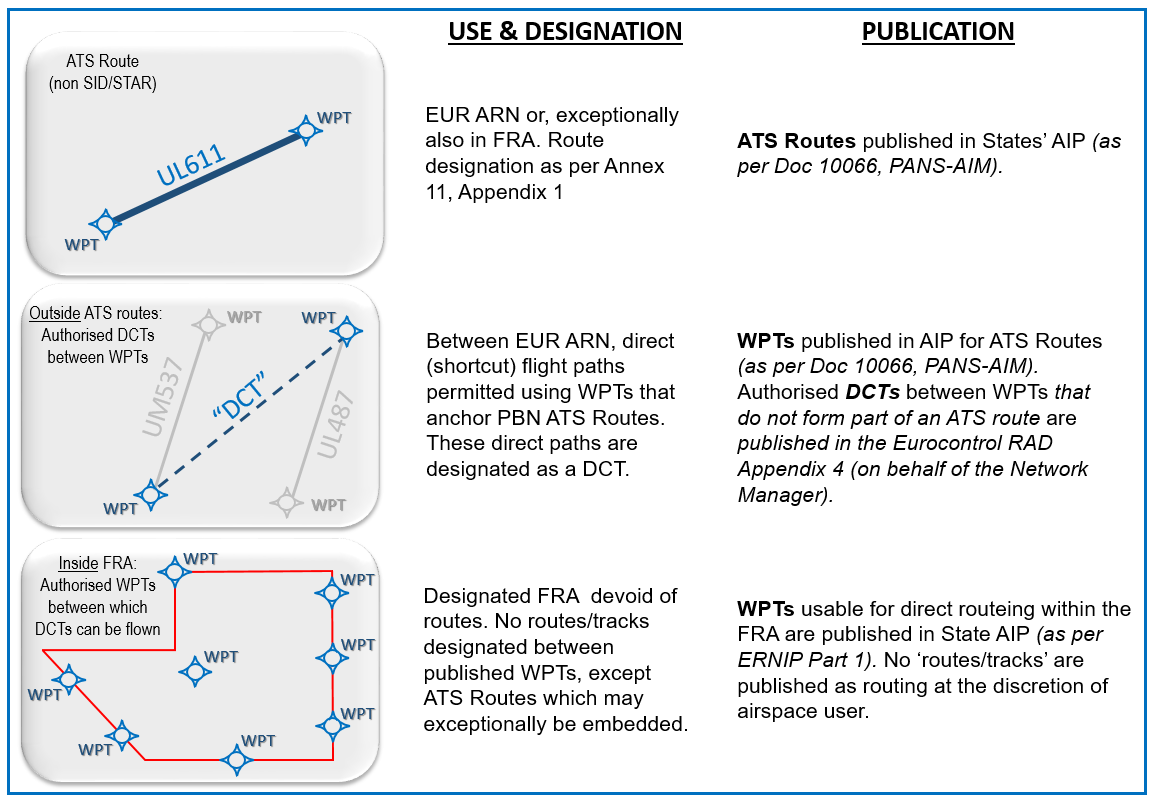
PANS-ATM’s definition of an ATS Route includes SIDS/STARs. SIDS/STARs form a subset of ATS Routes. In European Airspace, other kinds of flight paths exist: those that are defined by the airspace users in Free Route Airspace (FRA) and ‘DCT’ tracks that are authorised for use, typically, but not exclusively, between Waypoints in the ATS Route Network. European Airspace requires that all en route operations be predicated on PBN.
Free Route Airspace (FRA) and ATS Route Networks
The development of the Free Route Airspace concept and its perceived flexibility has led to a ‘mandate’ on the implementation of Free Routes Airspace (FRA). Airspace regulated by the European Commission’s CP 1 IR ((EU) 2021/116) is required to operate as Free Route Airspace in a two-stepped approach with December 2022 and December 2025 milestones. Importantly, the FRA is designated, and users select their flight path between any of the WPT’s published as entry/exit/other points to or within the FRA.
The picture below shows high level differences between FRA and ATS Routes which are not SIDS/STARs.
A key question which arises is when an airspace concept for PBN implementation would opt for a fixed published ATS Route Network as opposed to a FRA.
PBN specified Area Navigation ATS Routes
PBN specified area navigation ATS Routes tend to be designed where there is a need to systemise a network of routes and to strategically deconflict the traffic flows. This usually occurs when capacity and complexity is crucial. Systemisation and strategic deconfliction means that the vertical and or lateral ‘separation’ between the flight paths is ‘built into’ the route placement i.e. the airspace design. Typical examples of systemisation include parallel route networks spacing the flight paths at a specified distance, or choosing the crossing points between routes and controlling the vertical interaction between the two routes with level restrictions. More detailed information on strategic deconfliction of proximate flight paths are published in the 'European PBN Route Spacing Handbook' (Handbook 3, 2019).
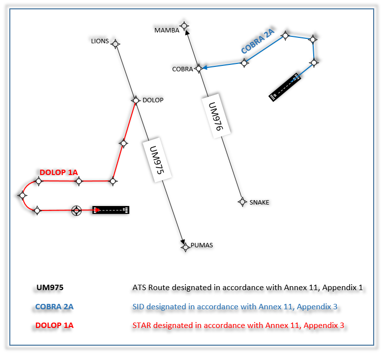
These possibilities exist because in the on-board area navigation computer (on which PBN relies), a required lateral navigation performance can be associated with an ATS route that has been designated and published as per ICAO Annex 11, Appendix 1 or Appendix 3 [Lateral navigation performance pertaining to SIDs/STARs and IAPs, is detailed in Attachment 5 of Handbook No 1]. Vertical constraints can also be designed into SIDs and STARs using ‘windows’ that prescribe at or above, at or below, or at altitudes for crossing tracks (though there may be other applications other than crossing tracks).
This possibility of ascribing performance stems from the fact that the process of designing (using PANS-OPS Criteria) and publishing (using Annex 15 standards and Doc 10066 processes) means that ‘matching’ ARINC 424 coding norms can be used to load these ATS routes in the on-board navigation database as either an ‘airway’ or ‘airport’ record. Once a data record exists, particular navigation performance and functionality attributes are associated with each leg of these ‘airway/airport records’ such as the navigation accuracy required along a flight segment e.g. RNP 1, or a particular way of executing a turn at a waypoint along the route (e.g. using a Fly By, Fly Over or Fixed Radius Transition – see Attachment 5).
Published ATS Route networks are planned at continental, regional or national level as appropriate. The introduction of PBN means that the more widespread the planning for the use of a common navigation specification as a basis of the network's design, the more seamless the interface between different areas can be because the route spacing would not be altered; Connectivity is key.
PBN does not change general good practices that uni-directional routes are better than bi-directional routes or that points of conflict between routes or parallel routes should be under the control of a single controller. Note that all EUROCONTROL route spacing studies are based on the assumption that sector lines will not be drawn between parallel routes so that the traffic interaction remains with a single controller.
Flight Paths within FRA or DCT Tracks
Other flight paths, such as DCT tracks permitted between set WPTs or trajectories in the context of FRA, neither seek nor provide a systemisation or strategic deconfliction of tracks. Users are offered the opportunity to route directly between published waypoints, which is more flight efficient. In fact, these flight paths can cross anywhere, and the burden lies with the controller to deconflict the traffic tactically. This is only possible in Europe thanks to the required availability of radar ATS surveillance as well as PBN’s broad navigation infrastructure providing a “mesh” of navigation positioning enabling area navigation by the on-board navigation computer certified for a particular PBN specification. In European FRA, the aircraft must be certified to RNAV 5 to operate in the FRA.
In Free Route Airspace, there is no ‘airway record’ and therefore no published path for the aircraft to follow. The path followed by the aircraft is defined by the FMS, and the navigation accuracy is also determined as a function of factory settings of the FMS by its manufacturer. Where there is no airway record available in the navigation database, the FMS generally defaults to a standard lateral navigation performance accuracy, normally expected to be 2 NM in en route (where what constitutes ‘en route’ is decided by the FMS manufacturer). However, this default accuracy value might not be the same for every aircraft as there is no standardisation across manufacturers, airframes and avionics.
FRA can be adjacent to an en route ATS Route Network or be adjacent to a terminal airspace and directly connect to SIDS/STARs. Similarly, en route ATS routes maybe connected to SIDs and STARs.
Given that flight paths in an FRA have no airway record, functionalities or ‘leg types’ or ‘turn transitions’ cannot be pre-coded in the navigation database because the trajectory is not published. A published ATS Route, on the other hand, can include a Fixed Radius Transition (FRT) or, in a SID/STAR, a Radius to Fix (RF) path terminator. Both of these ensure predictable and repeatable turn performance: the FRT on an ATS Route which is not a SID/STAR, the RF on a SID/STAR. Either of these functions can only be associated with RNP specifications. The navigation performance not only permits turn performance to be coded (FRT or RF) but also the lateral navigation accuracy required along the flight legs.
Care must be taken when leaving an FRA and joining a fixed ATS route network, that the FRT, for example, is correctly coded into the ATS Route record so that the FMS can correctly execute the turn. Furthermore, as FRA is expected to abut with terminal area operations in the future (see AF#3 of CP 1), the transition from a flight path within a FRA flight linked directly to a STAR will require the similar levels of care when ascribing a radius to fix (RF) at the beginning of the STAR. See Turn Performance.
Continental traffic flows which service multiple origin and destination airports are best segregated where possible from the terminal routes to/from airports. This is to avoid mixing overflying traffic with climbing and descending traffic or fixed en route ATS routes and/or free route trajectories.
SIDs and STARs are not uniform. They can be very short and simple or they can extend, in extreme cases up to 200NM. Typically, SIDs/STARs will be found within 40NM of the aerodrome that they serve.
PBN's considerable advantage is that it permits a great liberty on the placement of the SIDs/STARS as there is no requirement for the published flight path to pass over ground-based navigation aids. Furthermore, PBN with its reliance on RNAV or RNP systems comes packaged with certain functionalities which improve the vertical interaction management and turn performance already alluded to in Connectivity tab.
Vertical Interaction
Whilst operators, environmental managers and procedure designers consider the placement of each SID/STAR and IAP in terms of flight efficiency, environmental mitigation and safety (obstacle clearance/flyability), ATC has to manage traffic along the family of the routes as a package. As such, the airspace design from an ATC perspective, needs to address the interaction between arrival and departure flows of STARs/IAPs and SIDs because inevitably, these flight paths cross.
Route placement to achieve any objective is simplified greatly by PBN which enables SIDS/STARS to be placed ‘anywhere’, terrain and flyability permitting. An aircraft on a PBN SID/STAR does not have to fly to or from a NAVAID, it can be placed anywhere that policy dictates it should be placed.
Different objectives such as flight efficiency, environmental mitigation, safety and air traffic management drive where the routes are placed. These objectives are not mutually exclusive though there may be a struggle to prioritise these. It is possible to design terminal routes and achieve most of the (apparently conflicting) objectives.
Optimally, arrival and departure flows are segregated laterally to enable vertical deconfliction for interacting flows. However, whilst this might be possible in a low traffic density environment, it becomes more complex in high density airspace where the number of crossing routes and route interactions is far greater, as is the traffic density.
Climbing (departing) aircraft gain height at a faster rate than they lose it on the descent in the arrival phase. Practically, this means that if a departing aircraft and an arriving aircraft were to cross when the arriving aircraft is 30 track miles from touchdown and the departing aircraft 30 track miles from take off, the departing aircraft would be, unrestricted on a 10% climb gradient, at FL200+ and the arriving aircraft would be at FL100 or below descending on a 3° slope. (See Vertical Interaction tool).
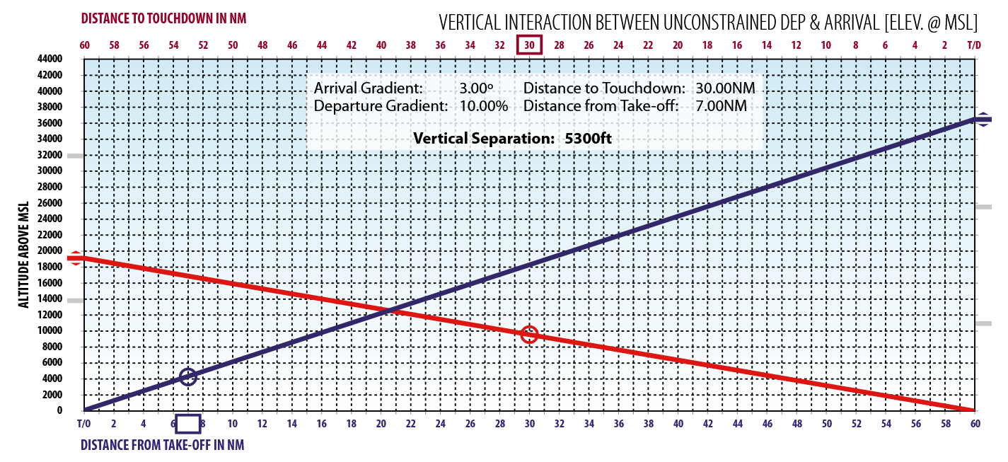
An aircraft entering downwind it is typically at 30NM from touchdown. If a departing aircraft crosses under it at this point after take off, the departing aircraft would be at 7NM from take-off and seek to be at 6000 feet or above a 10% climb gradient. This crossing point could be viewed as ideal: whilst vertical restrictions would need to be written into the SIDS/STARs to guarantee safety, in reality, the restrictions would do nothing more than replicate the unhindered climb/descent of the aircraft. This difference in rate of height gain and loss for departing and arriving aircraft means, for the airspace designers: that crossing points between arrivals and departures which are close to the airport have the SID cross below the STAR, and those that are far away from the airport would naturally have the SID cross above the STAR. In the latter instance, very careful consideration should be given to low climb gradients.
Overall, the vertical interaction principle is straightforward: the crossing point of SIDs and STARs should not constrain arriving or departing aircraft (hence, knowledge of aircraft performance is essential). The Vertical Interaction tool allows the user to put in specific climb and descent gradients. The Vertical Interaction tool shows all departure climb gradients in Blue and distance from T/O along the bottom X axis. Arrival descent paths are shown in Red and distance to touchdown indicated along the top access. Therefore, by setting climb and descent gradients and the distance of the crossing point from the T/O point (in blue) and the touchdown point (in red), the tool will calculate the expected vertical separation of the two flows at that point. Whilst the Vertical Interaction tool is not a procedure design tool, it will provide a good indication of the vertical interaction at the crossing. Two simple mantras can be considered when looking at crossing points:
- The larger the vertical separation at the crossing point, the less the workload for both controller and pilot.
- Keep crossing points either close in to the airport or far away from it, but not in between. The middle ground is the ‘workload’ ground as that is where both the departing and arriving aircraft will be at the same altitude and will require management.
The procedure designer along with operational pilots provide most of the aircraft performance data to the airspace design team. With PBN, some navigation specifications provide extra confidence in the vertical as well as the lateral planes and the use of these additional requirements can be of benefit in the airspace design.
Last but not least, it must be remembered that whilst PBN is a very powerful tool when used in the terminal airspace, it must be used judiciously. Early introduction of RNAV and RNP in the late 1990s saw the sometimes haphazard and excessive publication of PBN SIDS/STARs: in some cases, there were so many that the ATCOs could not keep track of them. The KISS principle applies no less with PBN SIDs/STARs: an airspace concept should be clean, crossing points should be limited, and the complexity of the design should be minimised. The PBN ‘tool’ should be used to simplify and not to render more complex.
Maintaining Runway Throughput
Typically, two predominant operating styles can be found when it comes to managing terminal airspace having ATS surveillance.
The first can be compared to a pressure cooker where a number of strategically placed holding patterns are spread geographically at a similar distance from the landing runway (nominally, at four ‘entry points’ to the terminal area. This is often referred to as the four-corner post). As the traffic increases, these holding patterns are stacked (filled) in order to keep the pressure on the terminal airspace and allowing ATC to feed a continuous stream of arriving traffic from the holding stacks to the arrival/approach system with departures threaded through the arriving traffic.
The second operating style is more ‘elastic’: in order to avoid holding aircraft, (sometimes extensively) longer terminal arrival routes are designed to the landing runway.
Sometimes these two styles are mixed.
The advantages and disadvantages of each style can be extensively debated. Some contend that in the end the track miles flown by arriving aircraft are more or less the same irrespective of the way in which the airspace is designed. However, when aiming to facilitate continuous descent, linear extensions on extended routing may provide the pilot with greater ability to plan the descent profile and hence provide benefits over holding, especially at lower altitudes.
Open and Closed STARs
PBN makes it possible to design closed and/or open procedures. Although ‘Open’ or “Closed’ procedures are not ICAO expressions, the terms are commonly used. The choice of open or closed procedure needs to take account of the actual operating environment and must include appropriate ATC procedures.
Open procedures provide track guidance (usually) to a downwind position from which the aircraft is tactically guided by ATC to intercept the final approach track. An Open procedure will require tactical vectoring instructions to align the aircraft with the final approach track. This results in the RNAV system only being able to calculate the descent up to the last published waypoint on the procedure.
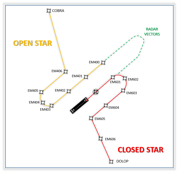
From this waypoint, the computer is coded to fly the last heading and height using a path terminator called ‘Heading to Manual Termination’ (VM) and now awaits manual intervention by the flight crew. This means that a continuous descent operation (CDO) after this point may not be possible, due to the uncertainty of path stretching which ATC may use. ATC may give distance to go (i.e. distance to touchdown) as a tactical enabler for CDO.
With the increase of technologies available to execute the final approach segment (e.g. ILS, GLS, RNP APCH,), vectoring to final approach has become more nuanced. There are some things which cannot be done when vectoring to join an RNP APCH or a GLS, which can, for example, be done when vectoring to an ILS. For more information on this topic, see PBN on the Flight Deck.
Closed procedures provide track guidance right up to the final approach track, from which the aircraft usually intercepts the ILS, but in the future, thanks to the PBN IR, they are more likely to continue an RNP APCH. The Closed procedure provides the pilot with a defined distance to touch down thus supporting the area navigation system’s execution of the vertical profile. Where multiple arrival routes are operated onto a single runway, the closed procedure can result in a safety hazard should ATC not be able to intervene to prevent the automatic turn onto final approach towards other traffic.
Significantly, however, Closed procedures can be designed and published in a manner that anticipates alternative routeing to be given by ATC on a tactical basis. These tactical changes may be facilitated by the provision of additional waypoints which allow ATC to provide path extension or reduction using instructions ‘direct to a waypoint’. However, these tactical changes, needed to maximise runway capacity, do impact on the vertical profile planned by the area navigation system, and the re-joining of a pre-defined flight path (STAR or IAP) at a particular waypoint, may be subject to certain conditions – see PBN on the Flight Deck.