The table to the right shows the different approach options and is formulated against the ICAO Annex 6 approach types:
- Type A - 2D or 3D operations down to 250 feet
- Type B - 3D operations only with minima less than 250 feet
It should be noted that Precision Approach (PA) can support Type A operations and there may be circumstances, such as obstacle clearance or aircraft category which does not allow a minima below 250 ft.
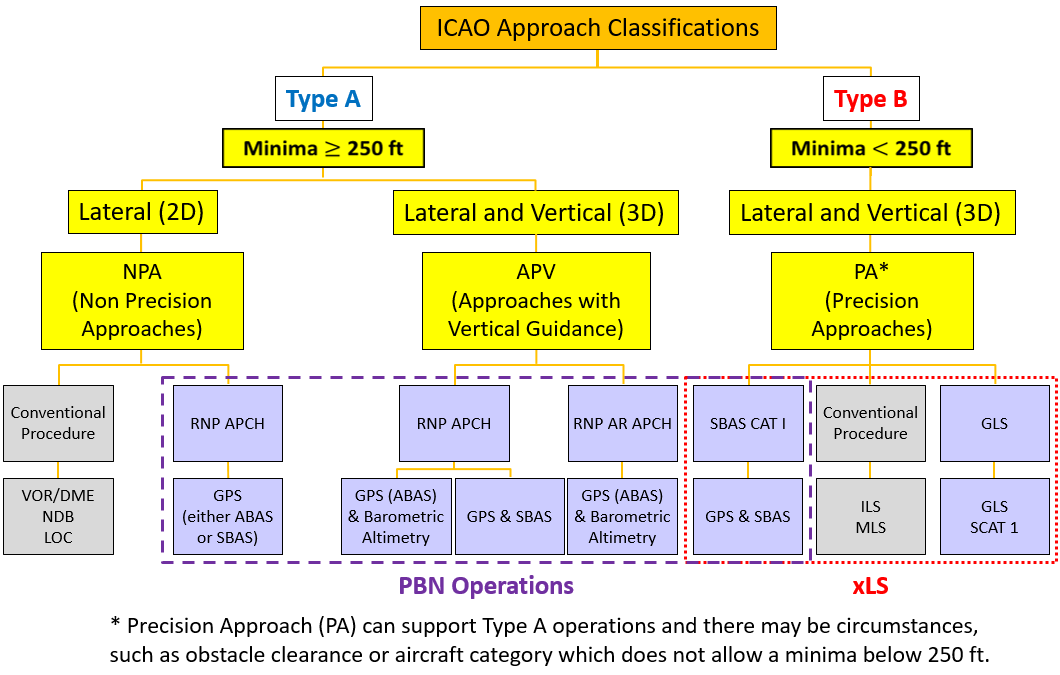
The blue dashed box indicates where PBN plays its role in the approach phase. In all cases, GNSS is the sensor.
The term xLS relates to any precision approach landing system.
If a pilot flies a 2D procedure, he/she is required by ICAO and EASA to manage the vertical profile as a Continuous Descent Final Approach (CDFA). CDFA can be achieved by applying a constant rate of descent or, if fitted, utilising the vertical navigation functionality; the use of VNAV on a 2D procedure is considered as a 3D operation.
Building on the Approach Options, the lines of minima that pilots will see on the different approach charts are as indicated.
The minima is the altitude/height at which the pilot is required to have the corresponding visual references (lights, runway, etc.) to continue the approach operation.
There are two different points at which the pilot must visually be able to see the runway or the approach lights depending on whether it is a 2D or 3D procedure:
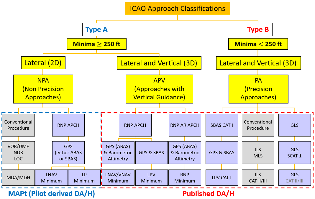
- 2D - The pilot follows the lateral path and must be able to visually acquire the runway at or before the minima to continue the approach operation. If the runway is not visually acquired by the Missed Approach point (MAPt), the pilot is required to execute a missed approach. The minimum shown on the approach chart will be LNAV or, in the exceptional case, LP.
- 3D - The pilot follows the lateral and vertical guidance designed to support that procedure to a point of decision, which is a defined altitude on the glide path. At that point, the pilot is to look up from his/her instruments and visually acquire the lights or the runway to continue the approach. There are different approach minima for 3D operations which are driven by how the aircraft is guided laterally and vertically. Those minima include: LNAV/VNAV, LPV, RNP 0.3 to 0.1, LPV CAT I, ILS, GLS, CAT II and CAT III.
If in either case, the pilot fails to visually acquire the runway or its approach lights at the point of decision, the pilot is to initiate a Go Around or Missed Approach.
There is an essential difference between a 2D and 3D procedure. In 2D procedure design, the designer calculates the lateral path to the runway end and then calculates the minimum obstacle clearance altitude (MOCA) which will maintain the aircraft clear of ground hazards. The designer can use step-down fixes to get the aircraft lower closer to the threshold.
The designer will then calculate the last point at which the prescribed missed approach procedure must be initiated in order to ensure that the minimum obstacle clearance is not infringed; this is the MAPt. The instrument procedure does not protect the aircraft below the MOCA. Therefore, for 2D operations the minimum is a Minimum Descent Altitude or Height (MDA/H) and the aircraft is unprotected if it goes below that minimum.
For 3D operations, the procedure designer calculates both the lateral and vertical path to the runway end. The pilot will be 'heads down' flying the lateral and vertical indications displayed to him/her. The pilot will remain 'heads down' until the decision altitude/height. At that time, the pilot will look up ('heads up') and will decide if he/she can see the runway and/or the lights and whether from that point it is safe to land. If no visual or it is unsafe, the pilot will initiate a Go Around (missed approach). However, because the aircraft has been in a stabilised vertical descent, at the point of decision the aircraft will still have a downward trajectory. This will continue until the engines 'spool up' following the initiation of that MA. Procedure designers take this height loss into account when they design 3D procedures.
Therefore, flying to a decision altitude or height (DA/DH) is different to flying to a MDA/H and pilots must be aware of this. Applying CDFA to a 2D procedure will probably require the pilot to add on a height loss to ensure MDA/H is not bust. This is sometimes known as a Derived Decision Altitude/Height and can, in some instances be charted as DDH.
%20Z%20RWY%2007C.PNG) RNP approach with CDFA technique to LNAV minimum
RNP approach with CDFA technique to LNAV minimum
Aircraft with RNP approach capability but without an approved vertical navigation (VNAV) function for final approach need to fly to the LNAV minimum depicted on the RNP APCH approach chart. In this case, flight crews will use a Continuous Final Descent Approach (CDFA) technique for vertical navigation. This can be accomplished by using an advisory Vertical Navigation (VNAV) function if the aircraft is equipped with such a function. If not, a CDFA can be achieved by flying a constant vertical speed (V/S) or flight path angle (FPA). The flight crew will make corrections to the V/S or FPA based on altitude-distance crosschecks using an altitude-distance reference table on the final approach chart. Typically, the aircraft needs to be fully configured (gear down, flaps out and approach speed) before starting the final descent. This video illustrates a approach flown using a CDFA technique based a constant V/S. It was recorded in the Bombardier CRJ200, flying the RNAV Z approach to RWY 07C in Frankfurt (EDDF).
Select the chart to the right to view the procedure.
 RNP APCH flown to a Lateral Navigation/Barometrical Vertical Navigation (LNAV/VNAV) minimum.
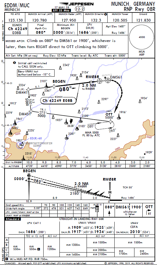
This video, recorded in the Airbus A350, illustrates the Airbus FMS Landing System (FLS) which was used to fly the RNP approach with LNAV/VNAV approach minimum to RWY 08R in Munich (EDDM). The extended final approach axis is intercepted from a radar heading which, using the FLS function, is similar as an ILS final approach intercept. This means that the extended (virtual) centreline of the RNP final approach segment can be intercepted both laterally and vertically by arming the Approach (APP) mode from any position upstream from the Final Approach Fix (FAF).
The vertical guidance of the FLS function is based on barometric vertical navigation (including cold temperature correction).
The guidance modes appearing on the Primary Flight Display (PFD) are F-LOC and F-G/S in analogy wih the ILS guidance modes LOC and G/S.
Select the chart to the right to view the procedure.
Localizer Performance with Vertical Guidance (LPV)
This video was recorded in the Airbus A350, illustrating the aircrafts LPV functionality on the RNP approach with LPV approach minimum to RWY 08R in Munich (EDDM). The intercept of the extended final approach axis is fully ILS look-alike. This means that the extended (virtual) centreline of the RNP final approach segment can be intercepted both laterally and vertically by arming the Approach (APP) mode from any position upstream from the Final Approach Fix (FAF).
The Final Approach mode indications "LOC" and "G/S" are also fully ILS lookalike.
The approach is flown to a Decision Height (DH) of 200ft, as LPV allows operations down to CAT I approach minima.
Another benefit of this technology is that the vertical path of the final segment is unaffected by temperature.
To view the approach chart (EDDM RNP Rwy 08R), select here.