In the majority of PBN specifications today, the focus is on lateral track accuracy only. It is only in the Final Approach Segment where vertical accuracy is prescribed. Longitudinal position error is not a major factor until considering Time-based Operations (TBO). However, longitudinal position accuracy should be taken into consideration when applying the most demanding levels of accuracy and introducing ‘managed’ turns. This applies to the RNP AR APCH specification using radius-to-fix (RF) turns.
When an aircraft is certified to a particular navigation specification, the manufacturer has demonstrated to the certifying authority that the aircraft can satisfactorily meet that level of lateral accuracy 95% of the flight time.
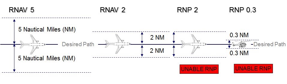
95% is selected as it provides a high confidence level of performance. It equates statistically to a 2σ (2 sigma) value. This means that 5% of the time the aircraft can be operating outside that performance level, and using the statistical analysis, we can work out how great that lateral track exceedance is likely to be. RNP specifications require the navigation computer to have additional functionality described as On-board Performance Monitoring and Alerting (OBPMA). This function in normal operations should alert the flight crew when the performance requirement of the route they are flying is exceeded. The probability of this alert not being given is 1 time in 10 million (10-7) per flight hour. However, in RNP operations there may be times when the system is operating abnormally, the required performance for the route is exceeded and the pilot is unaware of this. There is a integrity level for RNP that states if the level of uncertainty in position is two times the required navigational performance the system is to give an alert. The probability of this alert not being given in 1 time in 100 000 (10-5) per flight hour.
This then is one of the major differences between RNAV and RNP systems (they are both navigation computers): RNAV systems will not alert when the performance requirement is exceeded and therefore the flight crew may be totally unaware that they are not meeting the requirements of the airspace. RNP systems are more modern computers with a greater level of functionality and found on newer generation aircraft. The OBPMA functionality should provide the ATM system with a high level of confidence that the probability of an aircraft exceeding 2 x RNP without the flight crew being alerted is highly unlikely.
Accuracy
Accuracy is the difference between the estimated position (navigation output) and the true position of the aircraft. It is usually evaluated at the 95% level under fault free conditions.
Since accuracy is usually defined at the 95% level, it can be estimated by using: engineering analysis, computer simulation or flight trials. In fact, the development of a new navigation system for aviation usually involves extensive use of all three types of evaluation.
Accuracy is sometimes defined as the difference between the estimated position and the desired (rather than true) position of the aircraft.
GNSS provides the most accurate position estimation available to civil aviation. GPS with no external augmentation is expected to deliver a position estimation less than 20 m laterally from the true position of the user. With external augmentation, either satellite based or ground based, this position estimation is further improved down to metric levels of accuracy both laterally and vertically.
Integrity
Integrity is a key measure of flight safety. Integrity is the system’s ability to provide timely warnings when the system is not safe to use. Integrity risk is the probability of an undetected navigation system error or failure that results in hazardously misleading information on the aircraft.
Integrity is further quantified by the following key parameters: alarm limit, protection level, time-to-alarm, probability of false alarm, and probability of missed detection.
Continuity
Continuity of service is another key measure of flight safety. It is the probability that the system will function properly for the duration of the flight operation given that the system was functioning properly at the beginning of the operation.
Continuity risk is the probability of any detected, but unscheduled interruption, after the initiation of an operation.
There are three errors to be considered:
1. Path Definition Error (PDE):
This is the difference between the desired flight path the airspace planner or designer wants the aircraft to fly over the ground and the computer-defined path displayed to the pilot in the aircraft. The possible causes of this error are computer resolution, the unevenness of the Earth’s surface or magnetic variation. This is outside the control of the flight crew and the error resides in the data chain.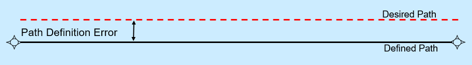
2. Navigation Sensor Error (NSE):
This error is the difference between the estimated position and the true position in a fault free environment. Each navigation sensor has its own defined sensor error and the performance requirements are stipulated in ICAO Annex 10. Simply put, GPS has the smallest NSE, DME/DME is more accurate than VOR/DME and VOR/VOR has the largest NSE for use in PBN. The Inertial is not a navigation sensor but has a stipulated drift rate of 1 – 2 NM per hour from the last update.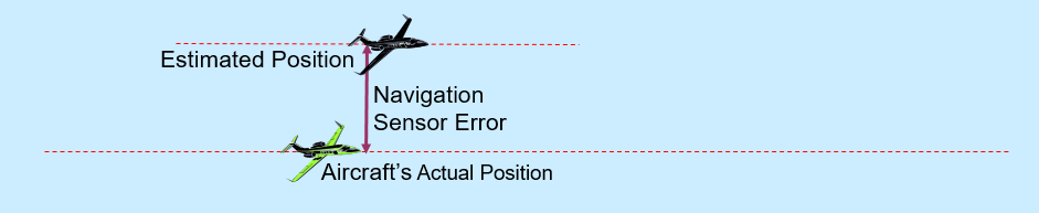
3. Flight Technical Error (FTE):
The third error to be taken into consideration is FTE. This is the physical ability of the pilot (manually) or the autopilot (automatically) to manoeuvre the aircraft from the estimated position onto the defined path. The use of an autopilot is considered the most accurate, using a Flight Director is slightly less accurate as there will be lag time between the computer indicating where the pilot is to fly and the pilot reacting. The least accurate management of FTE is manual flight where the pilot just follows a Course Deviation Indicator (CDI).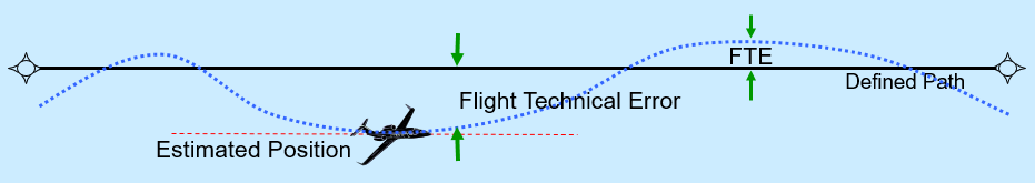
These three errors combined are the Total System Error (TSE) and it is against this that the certifying authority will issue an endorsement of that level of performance. Therefore, a RNAV 1 certified aircraft has demonstrated a performance of 1 NM 95% of the flight time with all of the errors combined. Similarly, an aircraft qualifying for a performance of 0.1 NM must demonstrate that all of the errors combined do not exceed this lateral track accuracy more than 5% of the flight time. To achieve 0.1 NM (which is RNP AR APCH) the navigation sensor has to be GPS, the aircraft must be flown using autopilot and the path data error must be actively managed.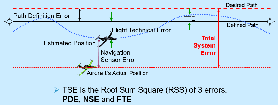
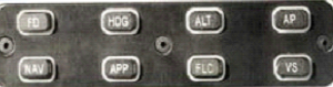
Flight Technical Error can be managed one of three ways; through the use of an autopilot (AP) following a Flight Director (FD) or manually reacting to course deviations indicated on an appropriate display.
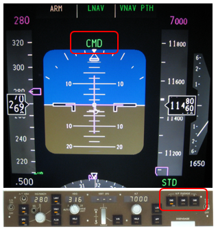 Autopilot (AP). When engaged (coupled), the Automatic Flight Control System (AFCS) automatically follows the lateral and vertical inputs from the Navigation Computer to follow the defined path. The value of FTE is automatically controlled and tailored to the flight phase.
As AFCS is not the most reliable of systems and to enable the largest number of aircraft to qualify for the navigation specifications, the vast majority of Navigation Specifications allow for manual flight. There are three exceptions:
- RNP 0.3
- RNP AR APCH
- Operations where the RF function is required (The A-RNP navigation specification calls out the requirement for the aircraft to have the RF path terminator).
 Flight Director (FD). On selection, FD provides pilot with lateral and vertical indications on the Primary Flight Display (PFD) to allow him/her to manually manoeuvre the aircraft to follow the flight plan in the navigation computer. The displayed information is similar to AP but the flight execution is not expected to be as accurate due to the lag time between the computer indication and the pilot beginning the manrouvre.
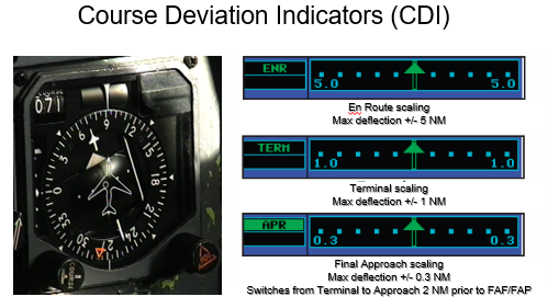 Manual Flight. The pilot flies the aircraft manually without the assistance of the avionics. The pilot follows navigation information fed directly onto a Course Deviation Indicator (CDI) whose sensitivity is set by phase of flight. PBN expects a pilot to be capable of maintaining within ½ full scale deflection on straight legs.
The management of FTE in manual flight is influenced by how the navigation computer is ‘coupled’ to the CDI, the scaling of the CDI and the pilot’s flying abilities. If there is a poor coupling then inaccurate information will be displayed to the pilot. If the CDI is not correctly scaled for the particular phase of flight, then maintaining the aircraft within ½ full scale deflection may not be meeting half of the TSE. Finally, pilot inattention or distraction may influence the lateral performance.
There are four ways an aircraft can transition (manoeuvre) between the straight segments of a route created in the navigation computer. Two waypoint transitions are called fly by and fly over. There are then two 'managed turn' performances which will ensure all aircraft follow the same path over the ground leading to a high level of repeatability and consistency of turn performance. For Instrument Flight Procedures (IFP) the designer can utilise the Radius-to-Fix (RF) path terminator. For en-route operations, a similar capability is provided by a function called the Fixed Radius Transition (FRT). RF and FRT are only to be used with RNP specifications.
![]()
This is the most common type of turn performance. Approaching the active waypoint, an aircraft will calculate a turn radius and angle of bank (AOB) subject to performance characteristics, airspeed, altitude, angle of turn and wind conditions. The aircraft will initiate the turn, prior to the waypoint, based on the calculated radius — this can be up to 20 NM before the waypoint. There will be a variation in the paths because each aircraft calculates its own turn radius (indicated by the green area in the figure within which the flight path of the aircraft will be located). This variation in turn performance becomes more apparent at higher altitudes and greater turn angles. The controller can expect the aircraft track to be on the inside of the waypoint.
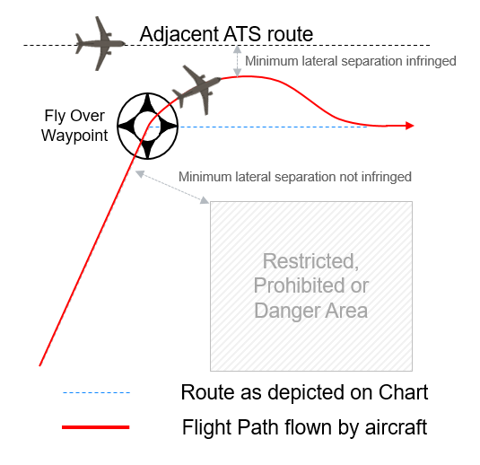
All aircraft are capable of executing a Fly Over transition. The aircraft will come to the overhead of the waypoint before initiating the turn onto the next leg. The aircraft will execute a turn reversal to attain the next track. In the figure, if the minimum prescribed lateral separation is applied, it will be infringed upon as the aircraft manoeuvres onto its next leg. The controller can expect the aircraft track to be on the outside of the waypoint.
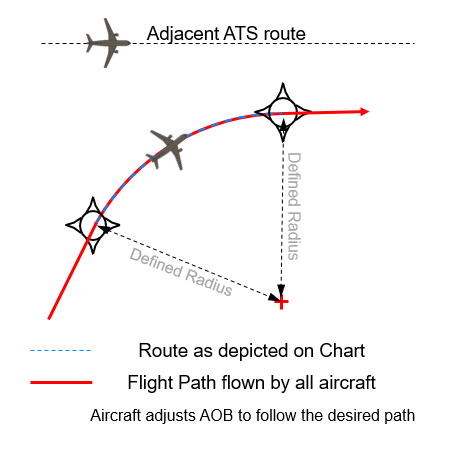
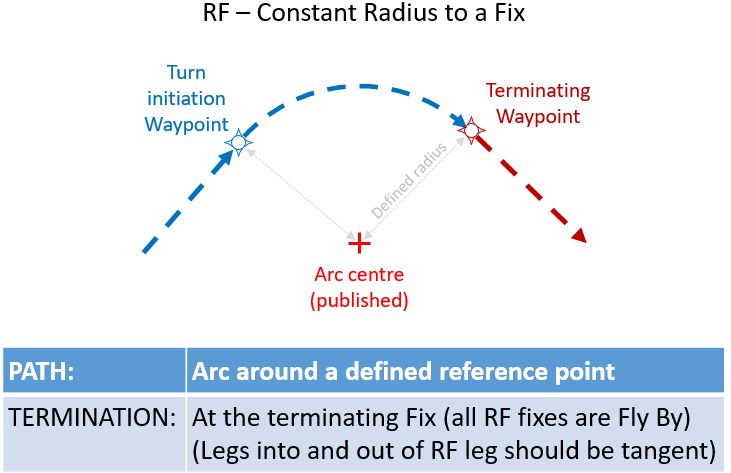
A RF is a path terminator used for instrument flight procedures (IFP). Path terminators define an action for the computer to undertake and a 'success factor' to define that action is complete; for the RF the action (path) is to fly a radius path around a defined arc centre and the 'success factor' (terminator) is the next fix (waypoint). Therefore, a RF is a curved route segment that is designed with a published radius and arc centre which are coded into the Navigation Database. The aircraft will initiate the turn at the waypoint defining the terminator of the previous leg and the initiation point of the curved segment. The aircraft will follow the published route until the next waypoint adjusting the AOB appropriately to maintain the defined path. This turn type is expected provide highly consistent and highly repeatable turn performance.
RF functionality can be applied to all RNP specifications applicable for terminal operations. Therefore, RF can be applied with RNP 1, RNP 0.3, RNP APCH (outside of the Final Approach Segment). RF is a required functionality for RNP AR OPS and A-RNP.
As with the RF, this computer functionality is only to be applied with RNP specifications. However, unlike RF the FRT is an immature functionality an is not expected to be used in European airspace in the near future.
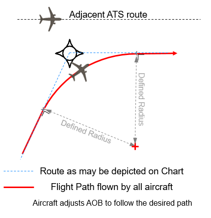
The FRT is published for en-route RNP ATS routes. Unlike the RF, where an arc centre is defined, the FRT has a turn radius specified by the airspace planner which is coded into the airways record for the ATS route waypoint. As the aircraft approaches the active waypoint, the FMC/FMS will calculate where the arc centre position and will initiate the turn at a point at which the inbound flight path is perpendicular to the radius which links the point to the calculated centre. The aircraft will then adjust the AOB to maintain the required radius until the aircraft arrives perpendicular to the calculated arc centre on the next leg. This 'managed' turn should provide consistent and highly repeatable turn performance and minimise or negate the variability of turn performance experienced with the fly by turn.
FRT can be applied to RNP 4, RNP 2 and A-RNP provided the aircraft has this functionality.
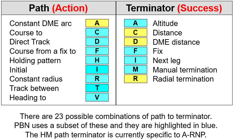
ARINC 424 defines a set of Path Terminators that describe the 'action' (the Path) the navigation computer must perform on each leg of an Instrument Flight Procedure (IFP) and the 'success factor' (the Terminator) for that leg.
These industry codes were originally designed to enable a computer to fly a conventional procedure. Therefore in PBN, we use a subset of the 23 possible path terminator combinations. The turquoise coloured Path and Terminators in the Table to the right are possible combinations called out in the different Navigation Specifications.
These specific Path Terminators are explained diagramatically in the expanded text boxes below and the specific PT requirements of each individual Navigation Specification can also be found below.
The required and optional Path Terminators for the individual Nav Specs are shown in the table below. 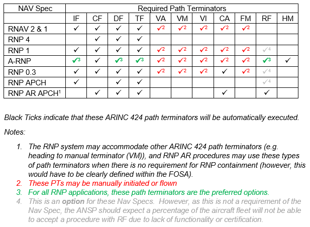
PANS OPS ICAO Doc 8168 Vol 2 stipulates the Path Terminators that can support the initial and final legs of a PBN IFP (RNAV or RNP SID, STAR, Approach or Missed Approach). This table is shown below:
|
RNAV & RNP procedures |
Initial leg |
Final leg |
|
SID |
CA, CF, VA, VI |
CF, DF, FM, RF (RNP only), TF, VM
|
|
STAR |
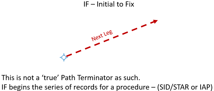
IF |
CF, DF, FM, HM, RF (RNP only), TF, VM
|
|
Approach |
IF |
CF, TF, RF (RNP only) |
|
Missed approach |
CA, CF, DF, FA, HM, RF (RNP only), VI, VM |
CF, DF, FM, HM, RF (RNP only), TF, VM |
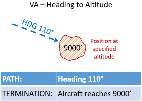
Heading. The direction in which the longitudinal axis of an aircraft is pointed, usually expressed in degrees from North (true, magnetic, compass or grid).
VA Leg - Defines a specified heading to a specific Altitude, termination at an unspecified position.
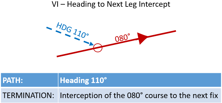
Heading. The direction in which the longitudinal axis of an aircraft is pointed, usually expressed in degrees from North (true, magnetic, compass or grid).
VI Leg - Defines a specified heading to intercept the subsequent leg at an unspecified position.
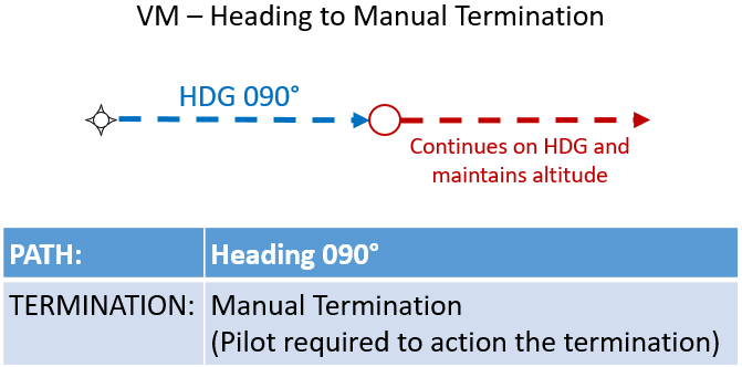
Heading. The direction in which the longitudinal axis of an aircraft is pointed, usually expressed in degrees from North (true, magnetic, compass or grid).
VM Leg - Defines a specified heading until a Manual termination.
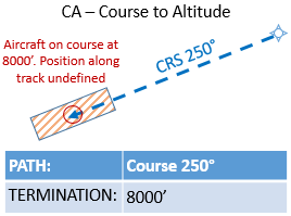
Course. The intended direction of travel of an aircraft, expressed in degrees from North (true, magnetic or grid).
CA Leg - Defines a specified course to a specific altitude at an unspecified position.
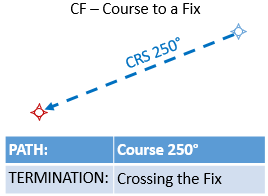
Course. The intended direction of travel of an aircraft, expressed in degrees from North (true, magnetic or grid).
CF Leg - Defines a specified course to a specific database fix.
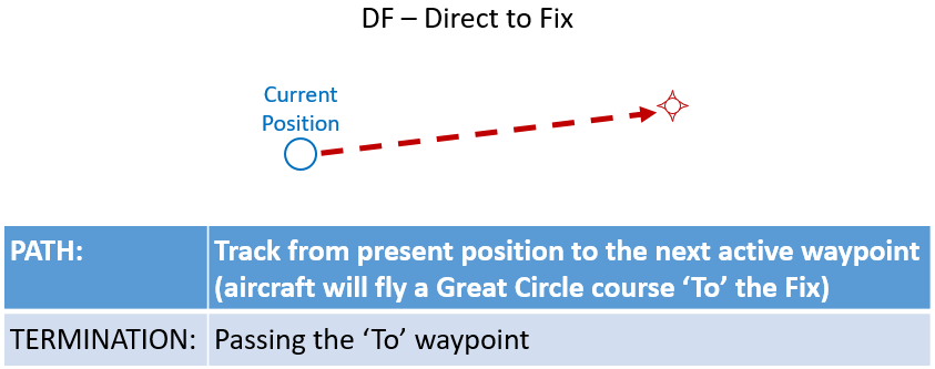
DF Leg - Defines an unspecified track starting from an undefined position to a specific database fix.
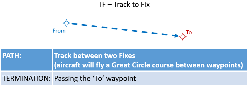
Track. The projection on the earth’s surface of the path of an aircraft, the direction of which path at any point is usually expressed in degrees from North (true, magnetic or grid).
TF Leg - Defines a great circle track over ground between two known databases fixes.
IF Leg - Initial Fix - Defines a database fix as a point in space.
RF Leg - Defines a constant radius turn between two database fixes, lines tangent to the arc and a centre fix.
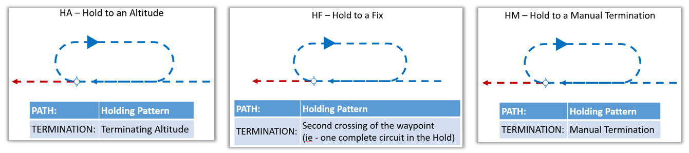
Holding in lieu of Procedure Turn (HF) for Approach Procedures and Mandatory Holds (HA, HM) in SID/STAR and Missed Approach coding. The HA, HF, and HM Leg Types define a holding pattern in lieu of procedure turn course reversal or a terminal procedure referenced mandatory holding pattern at a specified database fix. Leg time or distance is included as a data field.
The three codes indicate different path termination types:
- HA = Altitude Termination
- HF = Single circuit terminating at the fix.
- HM = Manual Termination.
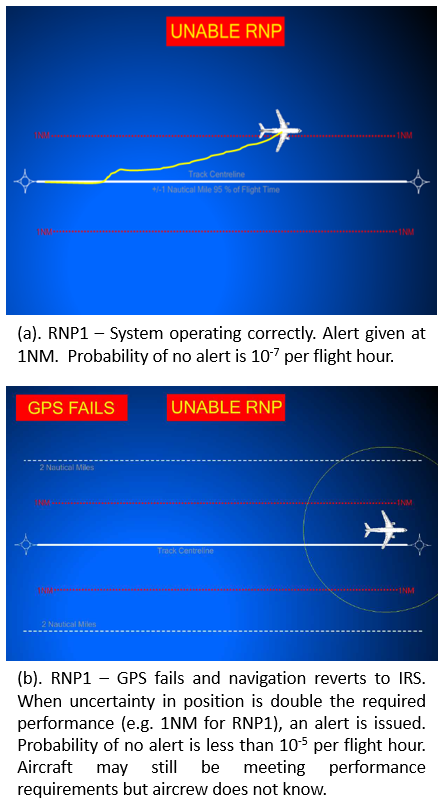 An on-board performance monitoring and alerting function (OBPMA) is required in all RNP specifications. It is an on-board functionality of the FMS and provides an alert to the flight crew when a required confidence in the position information is no longer met. If the navigation system is working correctly and using GNSS, then the probability of the aircraft position information exceeding the required performance without generating an alert is set at 10-7 per flight hour. However, if the navigation sensor was degraded PBN requires that an alert be given when the uncertainty in aircraft position exceeds double the performance requirement set for the route. The probability that this would not occur is lower than 10-5 per flight hour. In this scenario it is perfectly possible that the aircraft is still within the lateral performance requirement of the route but the aircraft does not know. The principle of on-board performance monitoring and alerting is illustrated to the right.