On-board performance monitoring and alerting when deviating from path
RNP specifications required On-board Performance Monitoring and Alerting. For example, the RNP system (or RNP system and pilot in combination) should provide an alert if the Total System Error exceeds the required navigation performance (RNP). This video, recorded in an Airbus A350, illustrates the aircraft indications (alerts) when deviating from the reference path with a distance greater than the required navigation performance (RNP).
There is no standard way in how aircraft perform turns, except when specific on-board functions are used which are associated to RNP navigation specifications, for example Radius-to-Fix (RF) or Fixed Radius Transition (FRT) capability.
Without RF or FRT functionality, aircraft will perform fly-by transitions at turn waypoints unless the waypoint is specifically denoted as a Fly Over waypoint. These fly-by transitions are variable and depend on factors like aircraft type, track angle change, true airspeed and wind. The variability is not unlimited as the trajectory in the turn has to be within the fly-by transition boundary.
EUROCONTROL has been analysing a variety of aircrafts’ navigation performance along straight tracks and in turns. Below is an illustration of recorded fly-by trajectories of various aircraft types, flown in professional flight crew training simulators. Tracks were recorded using both autopilot and manual flight supported by flight director. The fly-by transition boundary is indicated by the dotted line. It can be seen that the tracks are spread over the whole transition area. The simulation scenario and environmental conditions were exactly the same for each aircraft type. The tracks were recorded in the flight level range between FL200 and FL300 as the turn location is along an Standard Instrument Departure (SID) route where the aircraft are typically climbing to their cruise altitude.
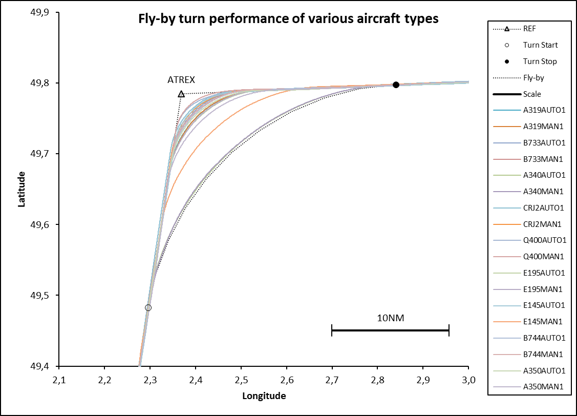
Fly-By turns produce a wide variety of turn performance and the earliest turn can be up to 20NM before the waypoint. Fly-by turns should remain within the Fly-By Transition Boundary, which is defined in RTCA DO-236C / EUROCAE ED-75D.
The EUROCONTROL Turn Calculator is convenient tool to display the fly-by transition boundary for a user specified turn geometry. The tool can also compute the characteristics of a constant radius turn, which is the alternative for fly-by transitions.
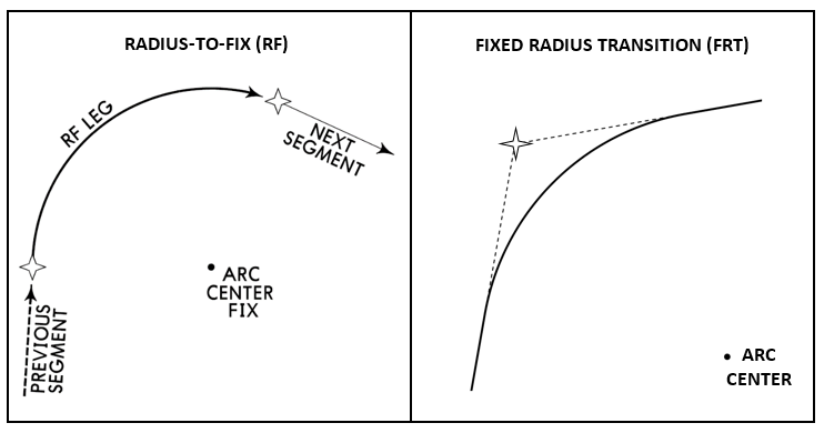
There are two types of constant radius turns:
- Radius-to-Fix (RF): this an ARINC 424 path terminator that can be coded for terminal procedures (SIDs, STARs, Instrument Approach Procedures) in the airport records of the navigation database. It is a defined path over ground from one waypoint to the next waypoint. RF is currently available in a wide range of aircraft including transport, regional turboprop and business jet aircraft. It is an optional function for the navigation specifications RNP 1, RNP APCH and RNP 0.3. It is a required function for the navigation specifications Advanced RNP and RNP AR. Note that RNP AR is the only navigation specification, which allows the use of RF in the Final Approach segment.
- Fixed Radius Transition (FRT): this is a turn with a constant radius, defined in the en-route airway record for a particular waypoint. There is no start and end waypoint (these are calculated by the navigation system). FRT is currently available on the high end aircraft (Airbus and Boeing). It is an optional function for the navigation specifications RNP 4, RNP 2, RNP 1 and Advanced RNP.
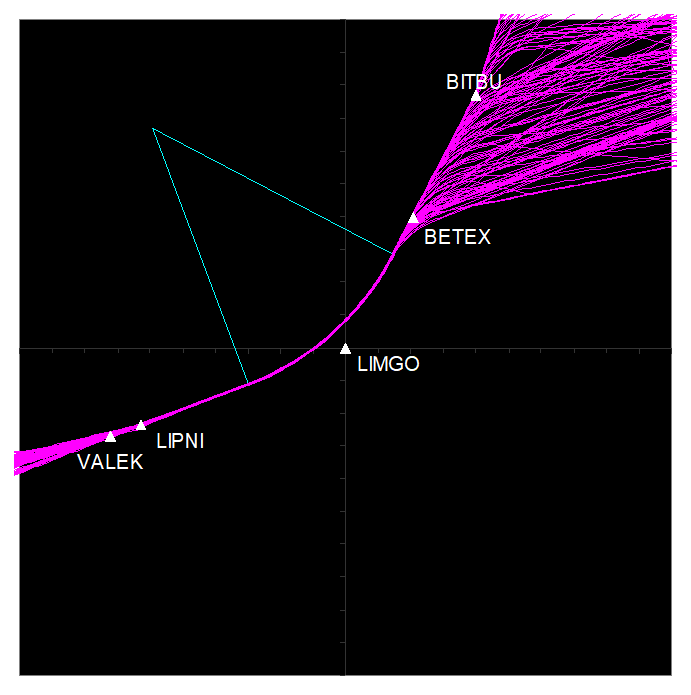 The illustration to the right is from a trial organised by EUROCONTROL in 2013 during which 144 tracks were collected of aircraft flying an FRT at waypoint LIMGO in Belgian/MUAC airspace. The spread of tracks around the centreline of the arc defined by a 22,5NM radius, is characterised by a standard deviation of 0.026 NM with minimum and maximum deviations of -0,12 NM and 0,1 NM.
A full report of the trial can be downloaded from here.
At EUROCONTROL, we monitor the performance of ground and space-based navigation systems in support of the implementation and operation of navigation applications relevant for the execution of the network functions.
For ground-based navigation, we assess the coverage of the navigation services provided by ground-based navigation systems in support of RNAV and conventional en-route applications. Our objective is to identify coverage gaps that could affect network operations. In addition to assessing the coverage of the network of ground-based navigation systems, at EUROCONTROL, we monitor also the performance of the services provided by the space-based navigation systems.
By doing so, we support the implementation and operation of PBN and other CNS navigation applications based on GNSS, such as ADS-B. The GNSS monitoring service provides following functions.
RAIM prediction
Our Receiver Autonomous Integrity Monitoring (RAIM) availability prediction service is made available to airspace users in order to satisfy related requirements set in AIR OPS for EU certified operators, and Regulation (EU) No 452/2014 for non EU operators. It is a web-based service accessible to operators for use during the flight planning process.
Support to the publication of GPS/RAIM NOTAMs
The predicted RAIM outages of more than 15 minutes are available to ANSPs in a format that can be distributed to airspace users via NOTAM. This service is though EAD on request of ANSPs and currently provided to several States. Our space-based navigation monitoring is powered by our AUGUR tool, which can be accessed from here.
In the future, the service will be further enhanced based on additional information to be provided by:
- The Galileo Reference Centre (GRC) for the core constellations of the Global Navigation Satellite Systems (GNSS);
- The European Geostationary Navigation Overlay Service (EGNOS) Service Provider for the EGNOS system.
GNSS Interference
GNSS Interference has multiple potential impacts on aircraft systems. However, given the variety of systems operating, the impacts will not be homogenous across all fleets and equipage. In some cases, the GNSS signal could be degraded but not completely lost, resulting in decreased position accuracy. The aircraft GNSS receiver itself is the main source of position information, which drives aircraft navigation system supporting Required Navigation Performance (RNP) operations and providing position input to different aircraft systems. Some business aircraft are even using GNSS as a reference source for aircraft flight control and stability systems. The most common impact is complete loss of GNSS reception, which results in loss of GNSS position, navigation and time.
GNSS Reversion and Pilot procedures
Pilots have an Aircraft Operations Manual specific for each aircraft and this document details normal and abnormal operational procedures, with explanations provided. In flight, however, pilots use the Quick Reference Handbook which contains in-flight procedures to be used in the event of abnormal or emergency situations.
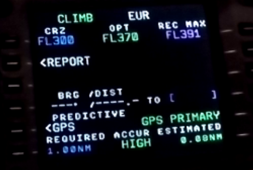
Some aircraft provide a clear indication when the GNSS signals are lost or no longer reliable, as illustrated below by the two pictures taken in an Airbus aircraft. A visual indication appears on both the Multi-purpose Display and Control Unit (MCDU) and the Navigation Display (ND).
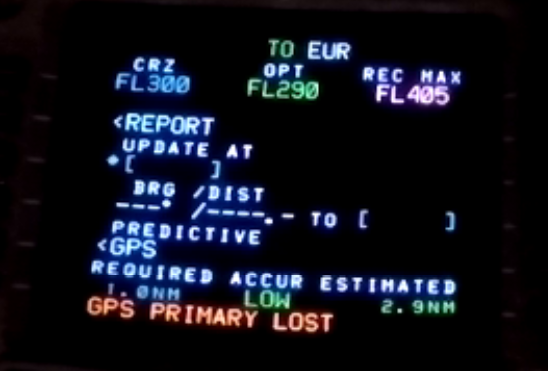
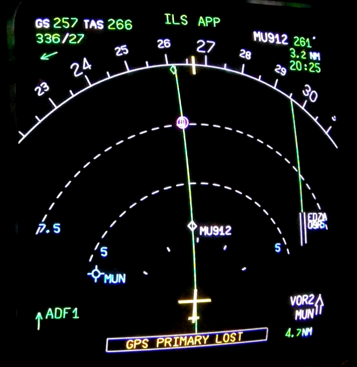
There are other aircraft in which the loss of GNSS is less obvious or even not indicated at all in the pilot’s primary field of view. Those aircraft will only issue an alert if the actual navigation performance exceeds the required navigation performance (RNP).
Manufacturers determine the avionics interface and decide how obvious this information is made. When becoming aware of that GNSS is unusable, a pilot is more likely to suspect a faulty receiver than a constellation problem, unless multiple receivers indicate a failure. Essentially, if the aircraft is unable to achieve the performance required of the navigation specification, the pilot will know this and inform ATC.
If GNSS fails, most avionics with alternative navigation means, will automatically default down to IRU with radio updating (e.g. DME/DME) or the pilot can ask for vectoring if navigation becomes impossible. In those avionics interfaces where the pilot is informed that GNSS is lost, the pilot will be likely to communicate this to ATC (depending on company procedure) even if the aircraft is capable of navigating and achieving the required performance.
This difference in avionics suits and pilot procedures is something that needs to be managed when ATCOs develop their local contingency operations and also when these are developed for the Network. It is important to remember that when GNSS becomes unusable, this can affect multiple systems including navigation and communication (e.g. message timing) and some surveillance and other systems e.g. ADS-B, TAWS, etc.
Industry provides AOs with awareness information on how the avionics deals with a GPS outage by publicizing operating instructions and additional awareness material for flight crew. This information could be applicable to a single model or to a family of aircraft; an example of this would be Airbus’s In-service Information.
The GNSS signals are used as well by some of the ground CNS systems. The main impact of a GNSS outage on these systems is the loss of the main time synchronisation source (time stamp).
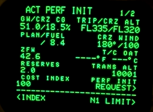
Aircraft are desinged to fly within a certain speed range. The heavier the aircraft, the higher the Flight Level and the higher the g-load, the smaller this speed range becomes. At the maximum flight level the aircraft is able to maintain for a certain aircraft weight and g-load, the minimum and the maximum speed will converge to what is called the “Coffin Corner”. The Flight Management Systems (FMS) in Airbus and Boeing aircraft have the capability for the flight crew to enter a Cost Index (CI) which is defined as the ratio between time and fuel related costs for an operator:
Cost Index (CI) = time related costs / fuel related costs
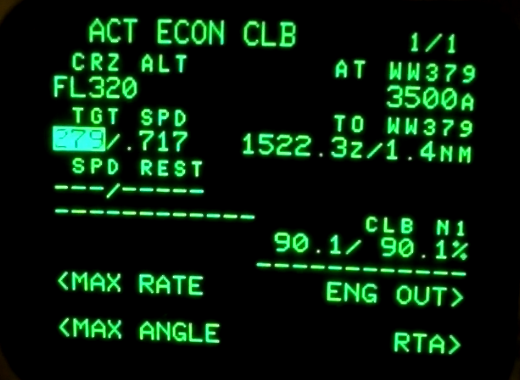
Once the flight crew has entered the aircraft weight, CI and winds, the FMS will use this data to compute optimum (“econ”) climb, cuise and descent speeds as well as an optimum (and in some aircraft a maximum) Flight Level, as indicated in the pitcures below.
Example: Airbus
Example: Boeing
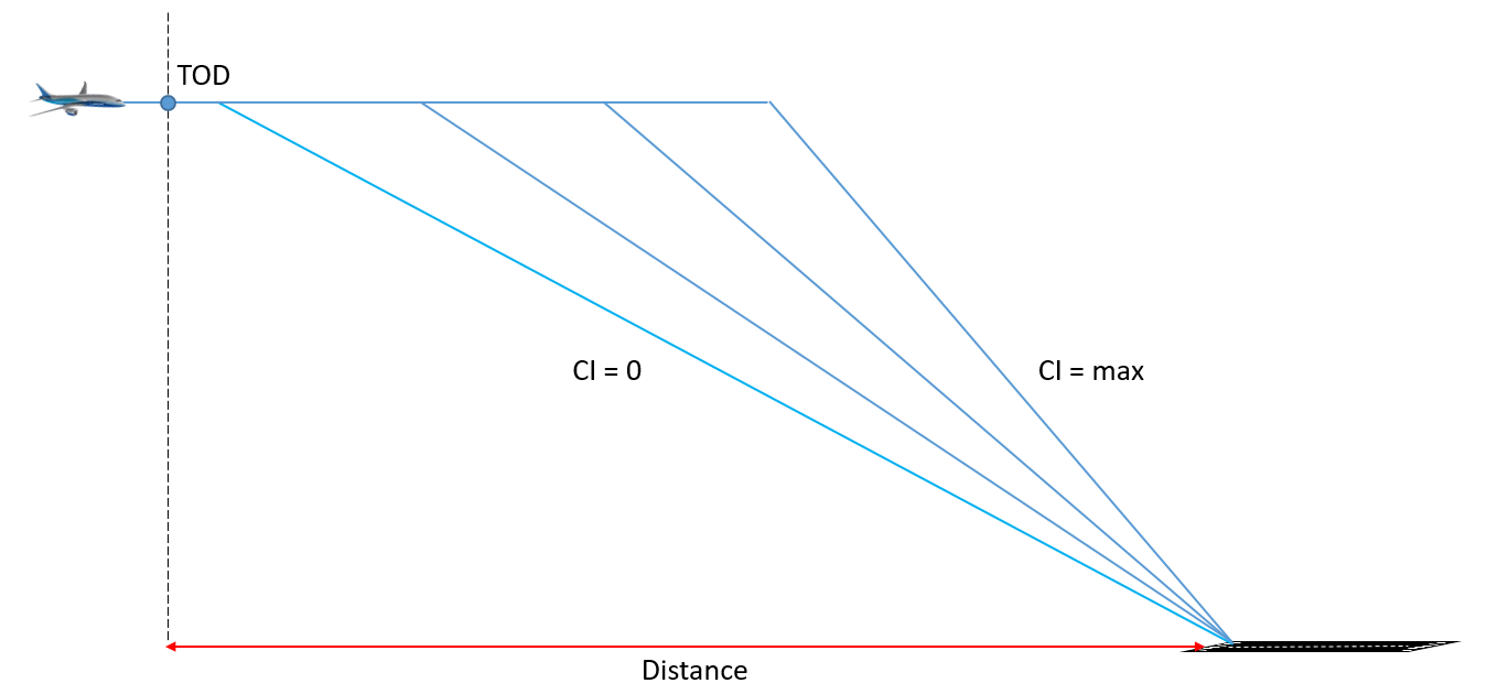
A low Cost Index (CI=0) will lead to low speeds (corresponding to maximum range speeds) whereas a high Cost Index (CI=99 or 999 depending on the manufacturer) will lead to maximum speeds. A low speed (low Cost Index) will also lead to an earlier optimum Top Of Descent location than a high speed (high Cost Index) as indicated in the figure below.
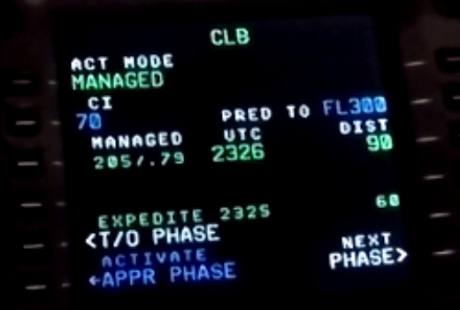
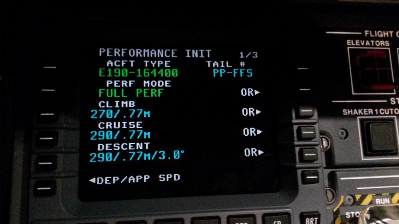
Note that the concept of Cost Index is typically used in Airbus and Boeing. In some other regional aircraft types, the speeds used for time and fuel calculations and flight guidance are based on pilot entered values. Usually IAS/Mach entries can be made separately for the three flight phases: climb, cruise and descent, as illustrated in the picture below.
PBN provides maximum benefits for airspace design when utilised in a fixed route environment. When ATS routes, designated in accordance with Annex 11 Appendix 1 or 3, are published in the State’s AIP then the Datahouses will create airways or airport records for those routes. Within these records, the stipulated required navigation performance for each leg of the ATS route or Instrument Flight Procedure can be coded. Airspace planners and designers can then strategically deconflict the flows of traffic taking credit for this required performance.
In a route free environment, there are no ATS routes. Points of Entry and Exit will be defined and DCTs may be published in the State’s AIP or in the Route Adherence Document (RAD). Datahouses are not permitted to create airways records for flight paths which are not designated in accordance with Annex 11 Appendix 1 or 3 in the AIP.
However, PBN does support Free Routes in that the aircraft is capable of flying point-to-point navigation using the area navigation computer. But because there is no airways record, there is no possibility to stipulate a specific navigation performance requirement for that path. In this case, aircraft will use default lateral navigation performance requirements coded in their FMS, which depend for example on the flight phase. These default lateral navigation performance requirements are not uniform and therefore a blanket statement on an expected default performance level cannot be made.
Thus in the European Free Route Airspace (FRA) concept of operations, ATC tactically separates aircraft from each other. This is because strategic de-confliction is not possible as these ‘free routes’ have no airways record and therefore no navigation performance standard to adhere to. In an attempt to ‘standardise’ the lateral navigation performance, Service Providers may require crews to set a required navigation performance to fly DCTs within a designated FRA. Notably, however, the ability to provide a common performance requirement along DCT paths within FRA depends on two factors: whether the flight crew can set this performance requirement in their FMS and no error is made by the flight crew in setting the performance requirement.